Service Offering
We provide Tools & Technical Expertise; Tools Rental & Log Analysis.Well Integrity
Complete Well Integrity Profile Multifinger Caliper 24 and 40 Arms, Electromagnetic Thickness, Cement Evaluation RBT, Noice/Temperature Cross Flow.
Saturation
Saturation Profile Neutron Pulse tool perfect for low salinity and tight reservoirs.
Production & Injection
7 Sensors Production/Injection Profile GR, Temperature, Gradio Manometer Density, Pressure, Capacitance, Flowmeter, CCL, AFT Green Tracer.
Pipe Recovery
Pipe Intervention Suite 1" Magnetic Free Point tool, Addressable Release tool, Radial Cutting Torch System.
Well Pressure Control Equipment
WPCE 2-1/2" 10k & 5" 5k Systems Complete systems including Grease Control Console, Tool Trap, Tool Catcher, 30 ft Lubricators, Grease Head.
Choke Manifold
3-1/2" 10k & 2-1/8 5k Complete 6 valves certified Chock Manifold with or without Shut Down.
Pricing Details
Our All inclusive Pricing Plan that covers you wellWhat can I do for you Today?
- Well Integrity Profile
- Saturation Profile
- Production Profile
- Pipe Recovery
- Rentals
- Log Analysis Service
Product Specifications
Complete list of the Tech Specifications for your understandingWell Integrity
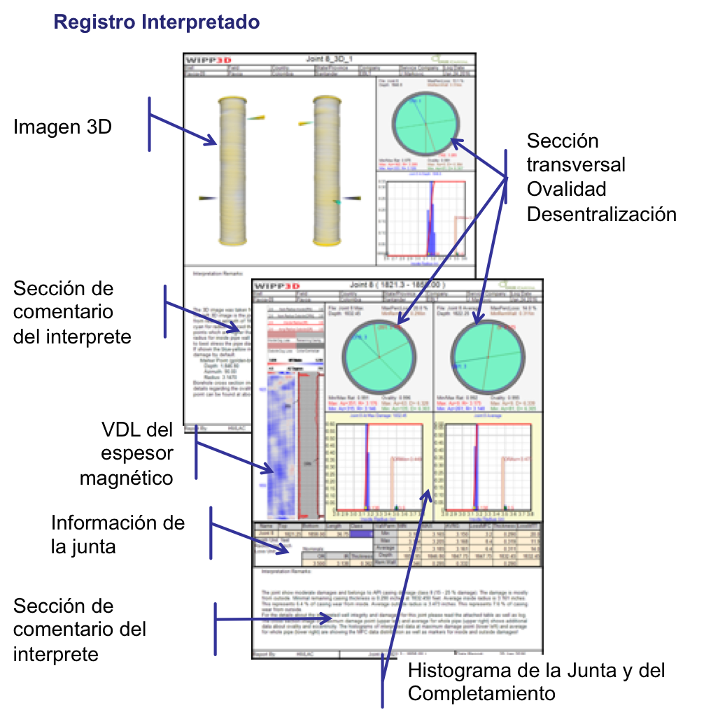
Complete well integrity suite, of 1-11/13" to 2-3/8" tools covering from 2-1/2" till 9-5/8" tubulars, high accuracy reading ± 0.04"; combined with electromegnitic thickness tools, either 1-11/16 multi-tubular or 2-3/8" single tubular tool. 12 Sectors radial bond tool combine with GR and CCL sondes. Web-based 3D imaging capabilities.
Saturation Profile
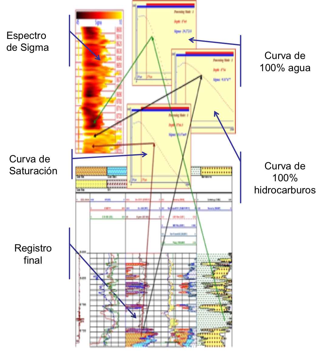
PULSE NEUTRON NEUTRON TOOL (PNN) measures Sigma, the ability of material to capture thermal Neutrons, in capture units (c.u.).
PNN counts directly the thermal neutrons reaching the detectors after their interaction with the surrounding formation; then, the usual inference by common Thermal decay tools that count Gamma Rays where High-counts means high-Sigma-Values changes by the PNN tool into High-counts means Low-Sigma-Values, and it has the significance of obtaining statistical uncertainties reduction for low Sigma values. This sole measuring approach allows better differentiation in environments of low Sigma values, which is the case when fresh water, oil and/or gas are present in the pore spaces, overcoming by this way, the low salinity formation water problem which appears as a limitation factor of standard Thermal Decay Time tools; additionally, Neutron readings are less affected by Neutron activation, hence, logging of Time-driven Stop-Checks in area of interest helps reduce the statistical uncertainties of readings at any desired depth spot. All of this makes pnnPlus tool, in conjunction with our PNN processing and analysis, a competitive behind-casing formation evaluation tool for high to moderate water salinity formations and the ultimate thermal decay tool for evaluation of lower salinity and lower porosity formations.
Application
Water saturation behind casing, porosity, remaining Hydrocarbon reserves estimation, Oil-water, gas-water and gas-oil contacts location, etc
Operation
The formation is bombarded with pulses of high-energy neutrons (14 MeV) generated by the tool. Neutrons interact
with the surrounding atoms and, during the lapse of time between high-energy neutron pulses, the thermal neutron
population that reaches the Neutron detectors is sampled by two detectors with 60 time channels each; Per Channel
Neutrons counted are used to compute the rate of decay, it is equivalent to measuring the rate at which thermal neutrons
are absorbed into the formation, the greater fluids and minerals capture thermal neutrons, the higher the value of Sigma.
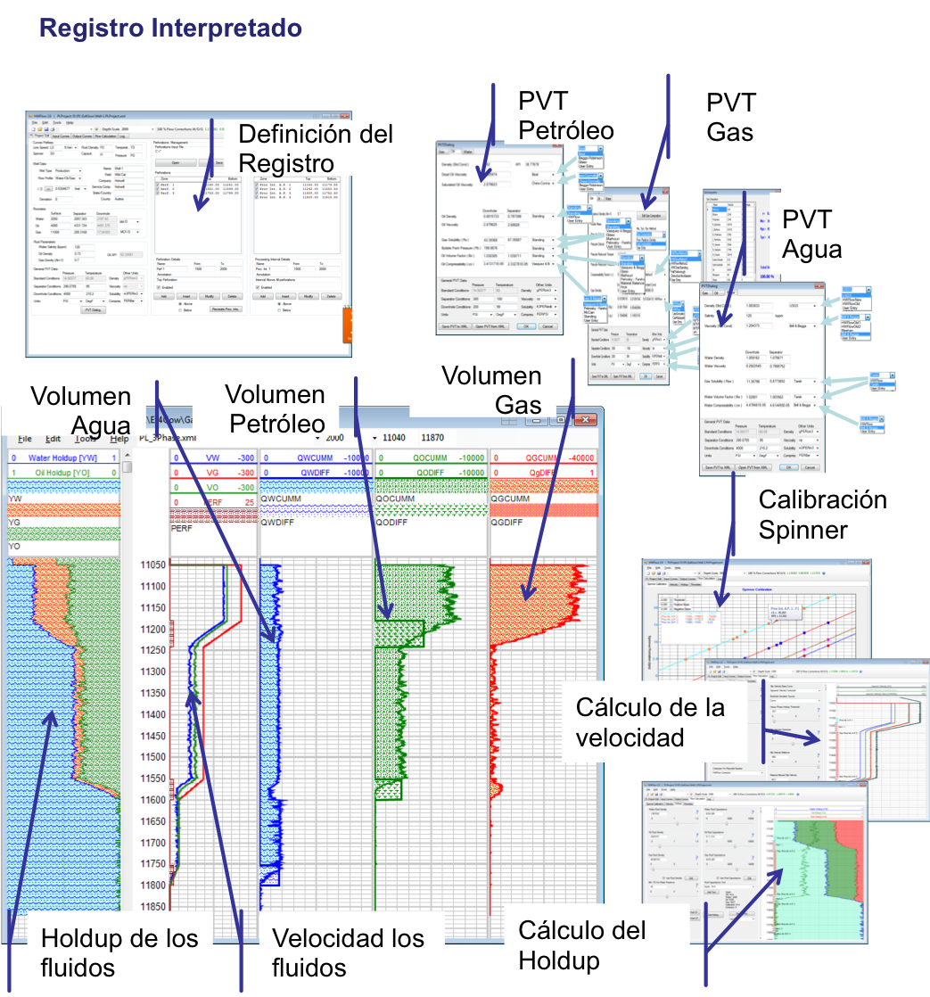
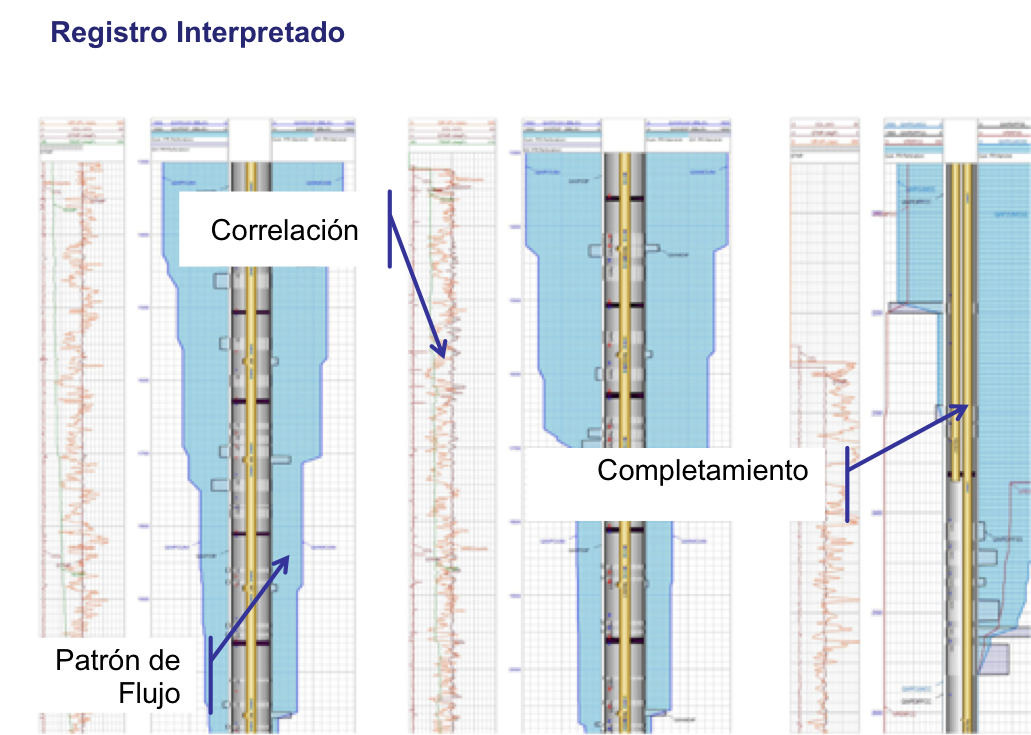
Production Profile
Application of production logsProduction logs are used to allocate production on a zone by zone basis and also to diagnose production problems such as leaks or cross flow. These various tasks can be split between those where the target production is into or out of the well and those where the flow never enters the well, typically flow behind pipe. The former is usually easier and more quantitative while the latter is more qualitative.
Fundamentals of production logging
Ideally we would like to measure radial inflow rates using a cheap and accurate sensor. Unfortunately no such sensor exists. Alternatively we could measure the axial flow rate in a well at a depths above and below the zone of interest and compute the difference and hence the inflow rate. Unfortunately there is not any practical measurement of axial flow rate beyond some special applications of oxygen activation logs. However it is possible to measure an axial velocity and combine this with an assumed or measured internal diameter to arrive at an axial flow rate. This last approach is most commonly used. Common velocity sensors include;
-->Turbine/Spinner flowmeters.
-->Markers/Tracers such as oxygen activation logs or radioactive iodine tracer logs.
--Heated anenometry
-->Turbines or Spinners are assumed to rotate at a speed proportional to the average fluid velocity passing through the swept area of the blades with an offset for friction/imperfections. This becomes a simple gain and offset transformation from the rotational speed of the spinner. Unfortunately the gain and offset are not constants but are a complicated function of fluid density, fluid viscosity, spinner pitch, pipe diameter, fluid velocity, etc. This means that the spinner is typically calibrated downhole by recording the spinner speed at a series of different logging speeds (usually 30, 60,90 ft/min or 10, 20, 30 m/min) and plotting the resultant average spinner speed versus the corresponding average logging speed to determine the slope (gain) and threshold (offset). The calibrated spinner velocity then needs to be converted to an average pipe velocity.The correction coefficient determined by the velocity profile across the pipe cross section can vary from 0.5 for an infinitely small spinner in laminar flow to 1.0 for a spinner that sweeps the entire pipe area. N.B. The prefix "full bore" when applied to a spinner is a marketing name. Full bore spinners rarely cover more than half the pipe cross section. If the cross sectional area of the spinner at the depth of the spinner blades occupies a significant fraction of the pipe area then the pipe area should be reduced before multiplying it by the spinner velocity and the correction coefficient.
Categories of applications
Production-logging tools find many applications from the time a well is drilled until abandonment and, occasionally, beyond. An appropriate categorization of production logs is by usage. This approach leads to the five distinct categories listed below that also represent a rough chronological order of tool evolution. Effective interpretation of the data from each type of log requires significant education and experience.
Diagnose production problems and allocate production
-->Monitor cement placement
-->Monitor corrosion
-->Monitor reservoir fluid contacts
-->Select zones for recompletion.
Injection Profile
Injection profiles are run to determine the health of injector units, monitor fluid dispersion, find and measure out of zone losses, and provide a comprehensive picture of the overall activity down hole on an injection well.
We wanted to take a minute to explain a few of the common surveys used in the injection profile package.
TEMPERATURE LOG
A record of the temperature gradient in a well. The temperature log is interpreted by looking for anomalies or departures from the reference gradient. Most anomalies are related to the entry of fluids into the borehole or fluid exit into the formation.
Since the temperature is affected by material outside the casing, a temperature log is sensitive to not only the borehole but also the formation and the casing formation annulus. Temperature logs have many applications, with the most common being to identify zones producing or taking fluid, to evaluate a cement or hydraulic fracture treatment, and to locate lost circulation zones and casing leaks.
OXYGEN ACTIVATION LOG
A phenomenon exploited for the purpose of detecting and quantifying the flow of water in or around a borehole based on oxygen activation. Oxygen (16O) can be activated by high-energy neutrons to produce an isotope of nitrogen (16N), which decays back to oxygen with a half-life of 7.1 seconds and emits an easily detected gamma ray of 6.13 MeV. The neutrons are supplied by the generator of a pulsed-neutron spectroscopy tool. The gamma rays are counted in detectors placed above the tool, for upward flow, or below it for downward flow. Various techniques have been developed to analyze the count rates in terms of water velocity, flow rate and distance from tool. The earliest methods were based of the ratio of the counts from two detectors. Stationary oxygen and other background signals are eliminated by calibration in a known zone of zero flow, by counting only in a window near 6.13 MeV, or by optimizing the detector spacings. More recently, impulse-activation techniques have been introduced. While they require the tool to be stationary, they are generally more accurate.
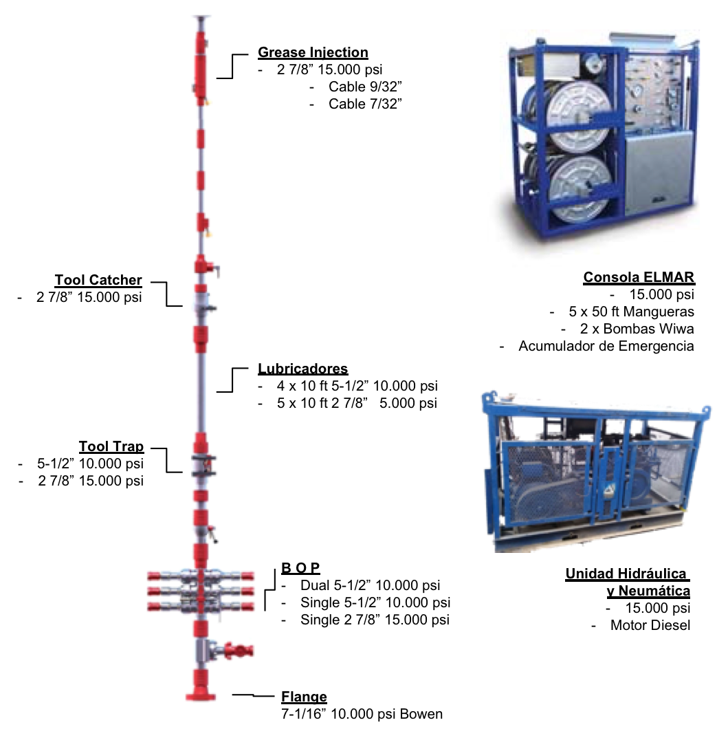
Electric-line & slickline pressure control equipment
Our PCE strings are designed for complete well pressure control during electric/stranded line operations on a live well. They are available with 5,000- and 10,000-psi working pressure ratings and in standard and H2S service. Inside diameters (IDs) range from 2-7/8 to 5-1/2 in.
-->The Enviro™ grease injection control head creates a seal around a moving wireline, along intervention access to wells under pressure.
-->The cable cutter sub (CCS) is designed for use in the event of wire becoming jammed in the grease injection flow tubes to the extent that no wireline movement (upwards or downwards) is possible. The wireline can be cleanly cut well above the wireline valve.
-->The ball check valve is a safety device for installation below the grease injection control head. It seals off the well in the event of the cable being broken/pulled out of the grease injection head.
-->The tool catcher is used to catch and hold the tool safely during pressure testing and in the event of the cable being inadvertently pulled off at surface. This prevents a possible fishing job.
-->Lubricators are used to insert and retrieve a tool string on a well under pressure.
-->Our hydraulic tool trap with external indicator protects the wellbore from inadvertent tool pull-offs.
-->The quick test sub is designed to save substantial rig time while pressure testing the WPCE string in multiple run operations.
-->Our lightweight wireline valves provide positive protection during well service operations and when operating with slickline, braided wireline, and electric line. Multi-line ram seals enable use of the same seal configuration for electric line and slickline.
-->The pump-in sub allows introduction of high volumes of fluid into the well via a hammer lug-type connection.
-->Our wellhead adapter flange provides a means of safely connecting the wireline PCE string to the wellhead.
A full range of slickline pressure control equipment is available, including wellhead adapters, wireline valves, lubricators, stuffing boxes, and other accessories.
Choke Manifold
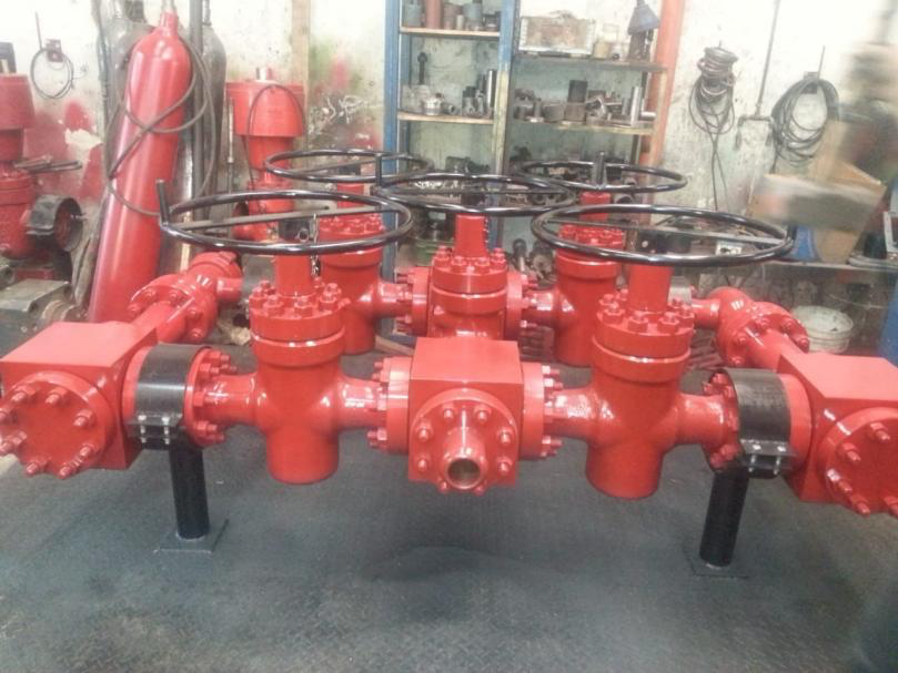 Choke Manifold
The Well Test Choke Manifold is the primary means of controlling the Well Flow at surface by operation (opening or closing) of the adjustable or fixed choke. Choke manifold is a system of valves and chokes for controlling the flow from the well usually has two flow paths, one adjustable choke used primarily for cleaning the well up and facilities to install and change choke of fixed sizes for a more accurate flow control during main well flow periods.
Warrior Panel
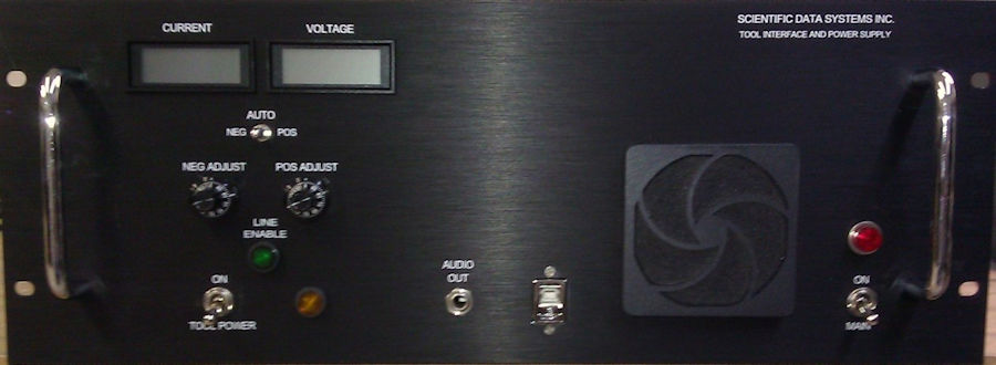 Casehole Warrior Panel
A compact tool interface and power supply which is a suitable interface for the most downhole tools. It uses the latest Digital Signal Processing (DSP) technology to minimize hardware complexity and maximize flexibility. The interface may be configured for open and / or cased hole services, and incorporates expansion slots for future developments and upgrades. Faceplate dimensions are 19” by 7”. Chassis is 17” by 17” by 7”, cable connections require another 2 to 3 inches of rack depth. The approximate weight of the panel is 45 pounds.
Winch Depth and Tension Panel
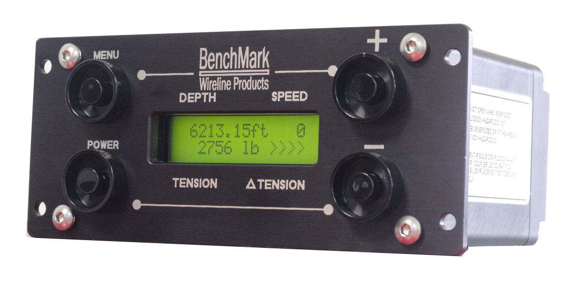 Winch Depth and Tension Panel
The BenchMark Wireline Compact Hoistman’s Display Panel is designed to be an independent depth, tension and line speed measurement indicator. The display panel is designed to be mounted inside or outside of a wireline unit and connect to a measuring head. It will work with all the BenchMark AM3K and Slickline measuring heads. The panel can be used as a secondary (backup) display for these devices. Depth input comes from either an optical encoder or a BenchMark backup sensor. Tension input comes from either an electronic load pin or a pressure transducer connected to a hydraulic gauge. The panel provides encoder and tension outputs. It also provides an output to connect to a 0-1ma electrical tension meter. The unit is powered by three internal rechargeable batteries. It can be connected to an external AC or DC power source to keep the batteries charged. The 606 model which is DC powered is Zone 2 Certified. The 603 has AC/DC power and is not certified. The panel has a built-in data recorder that stores depth and line speed data in ascii text format. The panel also has a built-in internal clock that runs continuously whether powered up or not. This clock is used to provide a time and date stamp for every data record. A USB port is provided as a means to upgrade the internal software and to retrieve data stored internally.